Close
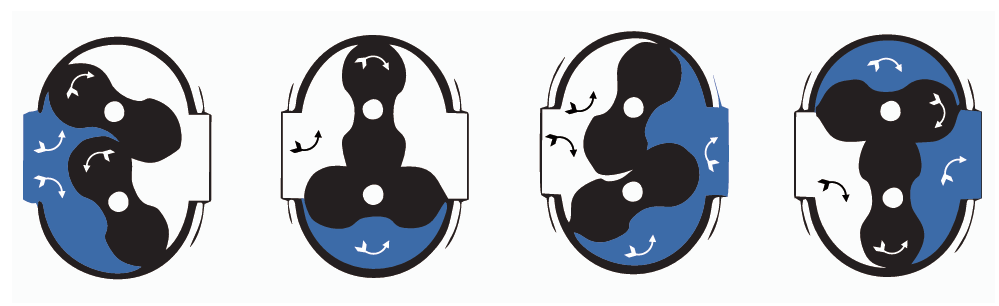
Two oppositely rotating impellers of figure of 8 shape are housed within a rigid measuring chamber with inlet and outlet connections on opposite sides. During impeller rotation, the precision machined measuring chamber traps a known volume of gas between the impeller and the adjacent chamber wall. The meter will measure and pass four equal gas volumes with each complete revolution of the impellers.
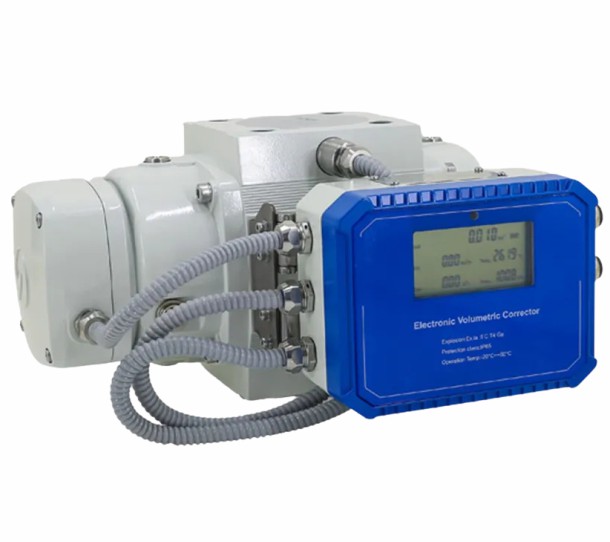
The sum total of the four volumes is the volume of gas flowing through the meter per revolution, Revolutions of the impellers are counted by a magnetically coupled gear reduction unit attached to the chamber. Temperature compensated units, and pulser units which allow remote volume data collection and monitoring are available.
A meter’s rated capacity is the maximum flow rate at which the meter may be operated and is determined by the dynamic loads acting on the moving parts of the meter. These loads are primarily related to meter RPM, and secondarily to the pressure of the gas being measured. The standard volume capacity of a rotary meter increases directly with changes in absolute line pressure and inversely with changes in absolute line temperature.
(1) Before installation, check and confirm whether the flow meter rotor rotates flexibly and without blockage. If there is any abnormality, please contact the manufacturer;
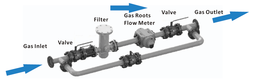
(2) The full-diameter LLQ series can be installed horizontally or vertically, During installation, the main shaft of the flow meter should be in a horizontal position. When installed vertically, the flow direction should be from top to bottom;
(3) Before installation, the pipelines before and after the flow meter should be purged to completely remove welding slag, iron cuttings, sand particles and other debris in the pipeline;
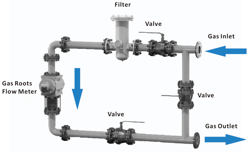
(4) To ensure the normal operation of the flow meter, a special gas filter must be installed upstream of the flow meter;
(5)To facilitate the subsequent maintenance and maintenance of the flow meter, it is recommended to adopt a dua-path design or set a by pass pipeline;
(6) When installing the flow meter, check to ensure that the flow direction marked on the gas flow meter is consistent, and check whether the flow meter usage conditions and installation environment conditions are in compliance;
(7) According to the installation position of the flow meter, the converter direction can be rotated to facilitate reading;
(8) After installation, the pipeline should be sealed and the air tightness of the pipeline should be strictly checked;
(9)After the flow meter is installed in the pipeline, please ground it properly.
Vertical
When vertical installation, the gas inlet end needs to be on the top, and the air flow from top to down, that is, upward and downward
The company recommends that users adopt vertical installation as far as possible, and vertical installation is conducive to the self-cleaning ability of the rotor on debris
Horizontal
When horizontal installation, the axis of the inlet and outlet end of the flow meter should not be lower than the pipe axis to prevent impurities in the gas from remaining in the flow meter and affecting normal operation.
At the same time, the flow meter flange should be directly connected with the filter flange.